7 Tips to Master Revit Reference Lines
Dec 01, 2025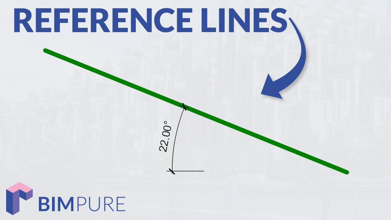
Reference Planes are used in almost all families. Reference Lines are more rarely used and tend to be more mysterious.
Typically, reference planes are represented by a dashed green line and the reference lines with a solid green line, although the line style can be modified.
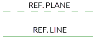
Reference planes have an infinite length.
Reference lines have a beginning and an end point.
You might think... Don’t reference planes have a length that can be modified in the family editor? Indeed, you can drag the extremities of a ref. plane to modify the visual length.

However, this is just a visual representation. The plane is actually infinite. You cannot align or place a dimension relative to the end points.
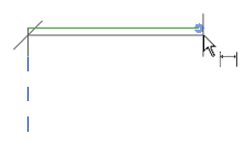
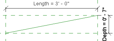
Things are different with reference lines. You can place a dimension between the beginning and end points. In this case, we place a dimension between a reference plane and the end point of a reference line:
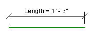
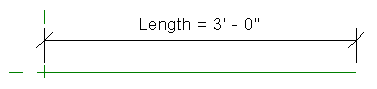
Reference Lines can have a dimension label for the entire length:
In this example, the end points of a reference line have been aligned and locked to the intersection of reference planes:
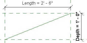
The reference line will always follow the intersection, even when the dimensions are changed.
Why is this helpful? Read on.
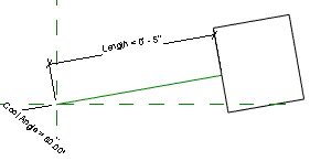
The most helpful way to use reference lines is when you need a rotation angle.
In this example, we lock one of the end point to the intersection of the ref. planes. Then, we add a length parameter to the reference line.
That’s when the fun begins. Add an angular dimension between the reference plane and the reference line.
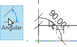
Add a parameter label to the angle. Here is the result:
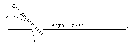
Try playing around with the angle value. The Reference Lines anchor point will stay fixed, and the angle you entered will be respected.
You can align, lock and constrain geometry and elements to reference lines the same way you can with reference planes.
You will use this strategy to create a door plan swing (see chapter xx).
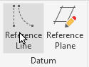
You can only use straight lines when creating reference planes.
However, you have a wider variety of options when creating reference lines:
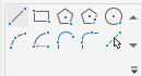
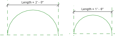
The most interesting option is to create an arc segment. As you can see, you can constrain the end points of an arc to reference planes. The arc will adjust when the length is changed:
If you want to see a wild workflow of reference lines for angles and curves, check out the Cavern Family Case Study.
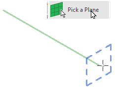
Each reference line has 4 different work planes. Two along the length of the line and one at the end of each point. This 3D view image of a ref. line illustrates the idea:

Ok... so what? Well, each workplane can be used to model geometry or place certain nested families. In this example, we set the active work plane to the end point of the line:
In this example, we create a random extrusion on the reference line end point work plane.
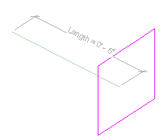
When the angle or length of this reference line is modified, the extrusion will follow along.
An advanced version of this strategy is to place a work plane-based nested family on one of the workplane to create a rotation easily. That's the strategy used in this tutorial to rotate families on any axis.
Enter your details below to get this free guide.